最近的科研告一段落了,实话实话,不太有多少成绩,完全算不是满意,不过过程还是比较快乐的。
马上要去实习了,所以把脱了这么久的OS lab做完吧。
然后再啃啃ULK和《Linux内核设计与实现》吧。
Lab 6: Network Driver (default final project)
这是最后一个独立完成的lab了。
OS不能没有network stack【no self respecting OS should go without a network stack】,在这个实验中,我们要写一个E1000网卡的驱动。
The card will be based on the Intel 82540EM chip, also known as the E1000.
Commit lab5中实现的内容,merge lab5到lab6 分支,并开始实验吧。
网卡驱动程序不足以让您的操作系统连接到 Internet。因此,在lab6 ,我们于新的 net/目录以及kern/中的新文件中为您提供了网络栈和网络服务器(a network stack and a network server)的code。
除了编写驱动程序之外,您还需要创建一个系统调用接口来访问您的驱动程序。您将实现missing的部分网络服务器代码以在network stack和driver之间传输数据包。您还将通过完成一个web服务器将所有内容联系在一起。使用自实现的Web服务器,您将能够从lab5中的文件系统内通过网络提取文件。
许多内核设备驱动程序代码几乎需要自己从头开始编写,并且这个实验提供的指导比以前的实验少得多:没有框架文件,没有一成不变的系统调用接口,许多设计决策都由您决定。出于这个原因,建议您在开始任何单独的练习之前阅读整个lab的描述。
QEMU’s virtual network
我们将使用 QEMU 的user mode下的network stack,因为它不需要管理权限即可运行。关于QEMU user-net的信息文档在这里。我们更新了 makefile 以启用 QEMU user-mode network stack和E1000 虚拟网卡。
默认情况下,QEMU 提供了一个运行在 IP 10.0.2.2 上的虚拟路由器,并将分配给 JOS 的 IP 地址为 10.0.2.15。为了简单起见,我们将这些默认值硬编码到net/ns.h中的network server内。
通过使用-net user 选项(即默认配置 ),QEMU将完全使用user-mode network stack。具体的虚拟网络配置如下:
guest (10.0.2.15)  <------>  Firewall/DHCP server <-----> Internet
                      |          (10.0.2.2)
                      |
                      ---->  DNS server (10.0.2.3)
                      |
                      ---->  SMB server (10.0.2.4)
The QEMU VM behaves as if it was behind a firewall which blocks all incoming connections.
虽然 QEMU’s virtual network 允许 JOS 与 Internet 建立任意连接,但 JOS 的 10.0.2.15 地址在 QEMU 内部运行的虚拟网络之外没有任何意义(即 QEMU 充当 NAT),因此我们不能直接从外部甚至是host,连接到在JOS中运行的network server。为了解决这个问题,我们将 QEMU 配置为在主机的某个端口上运行一个服务器,该服务器简单地连接到 JOS 中的某个端口,并在您的真实主机和虚拟网络之间来回传输数据。【根据上述提到的QEMU文档,我们得知这种从host某个端口到QEMU guest的重定向可以通过-netdev user,hostfwd=...来实现】
我们将在端口 7 (echo) 和 80 (http) 上运行 JOS servers。为避免共享 Athena 机器【和课程相关】上的冲突,makefile 会根据您的用户 ID 生成转发端口。要找出 QEMU 在您的开发主机上转发到哪些端口,请运行make which-ports。为方便起见,makefile 还提供了make nc-7和make nc-80,它允许您直接与在终端的这些端口上运行的服务器进行交互。(这仅用于通过nc连接到正在运行的 QEMU 实例,您必须提前单独启动 QEMU。)
Packet Inspection
makefile 还配置QEMU的network stack以将所有传入和传出的数据包记录到/lab目录中的qemu.pcap。
要获取捕获数据包的十六进制/ASCII 转储,请使用tcpdump,如下所示:
tcpdump -XXnr qemu.pcap
同时您可以使用Wireshark以图形方式检查 pcap 文,Wireshark可支持解码和检查数百种网络协议。
Debugging the E1000
我们很幸运能够使用硬件仿真。Since the E1000 is running in software, 因此仿真的E1000可以以用户能够读懂的方式将内部状态和遇到的任何bug报告给我们。通常,对于使用裸机编写的驱动程序开发人员来说,这是几乎不可得的。
E1000 可以产生大量调试输出,为此您必须启用特定的日志记录通道(logging channels)。Some channels you might find useful are:

例如,要启用“tx”和“txerr”日志记录,请使用make E1000_DEBUG=tx,txerr ....
注意:
E1000_DEBUG标志仅适用于 6.828 版本的 QEMU。
You can take debugging using software emulated hardware one step further。也就是说,如果您遇到困难并且不明白为什么 E1000 没有按照您期望的方式运作,您可以在hw/net/e1000.c中查看 QEMU 的 E1000 实现。
The Network Server
Writing a network stack from scratch is hard work. Instead, we will be using IwIP, 一个轻量级的开源TCP/IP协议套件(其中包含了一个协议栈)。在本实验中,lwIP可以看做是一个实现了 BSD 套接字接口并具有数据包输入端口和数据包输出端口的黑盒【具体的实现代码可以参考JOS内核代码中的net/lwip/目录】。
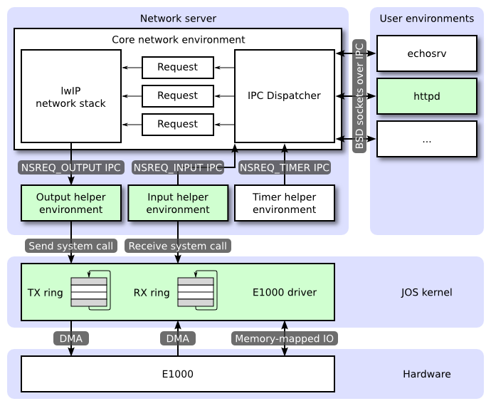
一个网络服务实际上是四个环境的组合:
- core network server environment (includes socket call dispatcher and lwIP)
- input environment
- output environment
- timer environment
下图显示了不同的环境及其关系。该图显示了整个系统,包括设备驱动程序,稍后将介绍。在本实验中,您将实现绿色高亮的部分。
The Core Network Server Environment
核心网络服务组件(Core Network Server Environment)是由socket call dispatcher和network stack(即这里IwIP)组成的。套接字调用调度程序(socket call dispatcher)的工作方式与文件服务器完全相同。用户环境使用存根stubs (定义在lib/nsipc.c中)将 IPC messages发送到核心网络服务组件。
如果您查看 lib/nsipc.c,您会看到我们找到核心网络服务组件的方式与我们找到文件服务器的方式相同:在系统初始化的时候,调用了i386_init——使用 ENV_TYPE_NS创建了 NS 环境,此后通过扫描envs,寻找这种特殊的环境类型(nsenv)。对于每个用户环境的 IPC请求,网络服务组件中的调度程序(socket call dispatcher)会代表用户调用 lwIP协议栈提供的相应 BSD 套接字接口函数。
//我们经过了一个又一个实验
void
i386_init(void)
{
	// Initialize the console.
	// Can't call cprintf until after we do this!
	cons_init();
	cprintf("6828 decimal is %o octal!\n", 6828);

	// Lab 2 memory management initialization functions
	mem_init();
	// Lab 3 user environment initialization functions
	env_init();
	trap_init();
	// Lab 4 multiprocessor initialization functions
	mp_init();
	lapic_init();
	// Lab 4 multitasking initialization functions
	pic_init();

	// Lab 6 hardware initialization functions
	time_init();	//这里已经完成过时间中断的初始化,即ticks = 0
	pci_init();		//这个是PCI初始化,也就是搜索所有用PCI连接的硬件[记录到root_bus中]

	// Acquire the big kernel lock before waking up APs
	// Your code here:
	lock_kernel();

	// Starting non-boot CPUs
	boot_aps();

	// Start fs. 【可以看到这里在初始化文件系统环境】
	ENV_CREATE(fs_fs, ENV_TYPE_FS);

#if !defined(TEST_NO_NS)
	// Start ns.【类似地初始化了网络服务组件的环境,记录core network environment到net_ns中】
	ENV_CREATE(net_ns, ENV_TYPE_NS);
#endif

	// Schedule and run the first user environment!
	sched_yield();
}

//最后ENV_CREATE会调用env.c中的env_create(uint8_t *binary, enum EnvType type),为特定的binary分配env结构,然后加载这个binary到特定的虚拟进程空间中。

//我们可以在 `lib/nsipc.c`中看到寻找核心网络服务组件相关的代码如下:
static int
nsipc(unsigned type)
{
    static envid_t nsenv;
	if (nsenv == 0)
		nsenv = ipc_find_env(ENV_TYPE_NS);
    /* …… */
}
常规用户环境下,是不会直接使用调用nsipc_*的【即lwIP协议栈提供的BSD套接字接口函数,可见于lib/nsipc.c,如nsipc_accept, nsipc_bind之类的】。相反,正常用户程序会使用lib/sockets.c中的函数,它提供了一个基于文件描述符的套接字 API。因此,用户环境可以通过文件描述符引用套接字,就像它们引用磁盘文件一样。有许多操作(connect,accept等)是特定于套接字的,但是对于另外一些操作如read, write等则通过lib/fd.c中正常的文件描述符设备调度代码进行。此外,就像文件服务器如何为所有打开的文件维护内部唯一ID一样,lwIP 也为所有打开的套接字生成唯一 ID。在文件服务器和网络服务器中,我们使用存储在struct Fd中信息将每个环境/进程的文件描述符映射到这些唯一的 ID 空间。
尽管看起来文件服务器和网络服务器的 IPC 调度程序的行为相同,但还是有一个关键的区别。BSD socket calls like `accept` and `recv` 可以无限制的阻塞。如果调度器让 lwIP 执行这些阻塞调用之一,调度器也会阻塞,整个系统一次只能有一个未完成的网络调用。由于这是不可接受的,网络服务组件会使用用户级线程( user-level threading)来避免阻塞整个服务器环境(server environment)。对于每个传入的 IPC 消息,调度程序创建一个网络线程并在新创建的线程中处理请求。如果线程阻塞,则只有该网络线程进入睡眠状态,而其他线程继续运行。【因此IPC dispatcher基本上都是多线程程序】
除了核心网络环境之外,还有三个辅助环境。除了接受来自用户应用程序的消息外,核心网络环境的调度程序还接受来自输入环境和计时器环境的消息。
The Output Environment
在服务用户环境套接字调用时,lwIP 将生成数据包交由网卡传输。具体来说,LwIP会将每个包传递给output helper environment ,即通过将数据包附加在 NSREQ_OUTPUT IPC 消息的page参数中,完成传递。The output environment会负责接受这些消息并通过我们即将创建的系统调用接口将数据包转发到设备驱动程序。
The Input Environment
网卡从网络中收到的数据包需要注入lwIP协议栈中,这就需要the input helper environment的帮助。
对于设备驱动程序接收到的每个数据包, the input environment将数据包pull出内核空间(使用您将实现的内核系统调用)并用过NSREQ_INPUTIPC 消息将数据包发送到核心网络服务环境(core network server environment)。
数据包输入功能与核心网络服务环境分离,因为 JOS 很难同时accept IPC 消息,并轮询或等待来自设备驱动程序的数据包。我们在 JOS 中没有实现select系统调用,以允许environments监视多个输入源,以识别哪些输入已准备好被处理。
如果您查看net/input.c和net/output.c,您会发现两者都需要实现。这主要是因为实现取决于你的系统调用接口。在实现驱动程序和系统调用接口后,您将为这两个辅助环境(即input/output environments)编写代码。
The Timer Environment
定时器环境定期向核心网络服务组件发送NSREQ_TIMER类型的消息,通知它定时器的时间已到(expired)。lwIP使用来自该线程/环境的计时器消息来实现各种网络超时。
Environment Creation Analysis
我们可以在整个网络服务的目录(即net)下看到net/serv.c中构建了多个环境,并且创建线程调度。
void
umain(int argc, char **argv)
{
	envid_t ns_envid = sys_getenvid();

	binaryname = "ns";

	// fork off the timer thread which will send us periodic messages
	timer_envid = fork(); //创建定时器环境
	if (timer_envid < 0)
		panic("error forking");
	else if (timer_envid == 0) {	//在定时器进程中
		timer(ns_envid, TIMER_INTERVAL); //定时启动ns环境
		return;	//然后返回
	}

	// fork off the input thread which will poll the NIC driver for input
	// packets
	input_envid = fork();	//输入环境创建
	if (input_envid < 0)
		panic("error forking");
	else if (input_envid == 0) {
		input(ns_envid);	//之后要完善这个函数
		return;
	}

	// fork off the output thread that will send the packets to the NIC
	// driver
	output_envid = fork();//输出环境
	if (output_envid < 0)
		panic("error forking");
	else if (output_envid == 0) {
		output(ns_envid);	//之后要完善这个函数
		return;
	}

	// lwIP requires a user threading library; start the library and jump
	// into a thread to continue initialization.
	thread_init();//线程初始化
	thread_create(0, "main", tmain, 0);	//线程创建,调用tmain,初始化整个协议栈等,并且调用serve()启动网络服务,接受各种系统调用。
	thread_yield();//线程调度【这里的调度策略很简单,就是保存当前线程到thread_queue,然后出队下一个线程,将这个线程的tc_jb字段的各种线程寄存器暂存值恢复到现有寄存器中,继续执行。
	// never coming here!
}
前面知道为了避免整个网络服务的阻塞,dispatcher会通过线程池来处理IPC请求。具体的线程实现定义在:net/lwip/jos/arch/thread.c中。
void
thread_init(void) {
    threadq_init(&thread_queue);//进去看这个函数
    max_tid = 0;
}
//lwpic/jos/threadq.h【线程池的管理操作就在threadq.c中】
static inline void
threadq_init(struct thread_queue *tq)
{
    tq->tq_first = 0;
    tq->tq_last = 0;
}

struct thread_context;

struct thread_queue //一个线程池,或许应该叫线程队列
{
    struct thread_context *tq_first;
    struct thread_context *tq_last;
};

struct thread_context { //线程结构体,即TCB
    thread_id_t		tc_tid;  //线程ID
    void		*tc_stack_bottom;	//线程栈
    char 		tc_name[name_size];	//线程名
    void		(*tc_entry)(uint32_t);	//线程指令地址 ,实现过线程这个很好理解
    uint32_t		tc_arg;	//参数
    struct jos_jmp_buf	tc_jb;//这个可以简单理解为,保存了各个寄存器的内容
    volatile uint32_t	*tc_wait_addr;
    volatile char	tc_wakeup;
    void		(*tc_onhalt[THREAD_NUM_ONHALT])(thread_id_t);
    int			tc_nonhalt;
    struct thread_context *tc_queue_link;
};
线程创建的代码如下:
int
thread_create(thread_id_t *tid, const char *name,
		void (*entry)(uint32_t), uint32_t arg) {
    struct thread_context *tc = malloc(sizeof(struct thread_context));	//分配一个空间
    if (!tc)
		return -E_NO_MEM;

    memset(tc, 0, sizeof(struct thread_context));

    thread_set_name(tc, name);	//设置线程名
    tc->tc_tid = alloc_tid();	//自己看

    tc->tc_stack_bottom = malloc(stack_size);//每个线程应该有独立的栈,但是一个进程的线程内存是共享的,因为共用一个页表。很明显的能够看出来,TCB没有页表,所以内存都是共享的,所以理论上来说,是可以跨线程访问栈的。
    if (!tc->tc_stack_bottom) {
		free(tc);
		return -E_NO_MEM;
    }

    void *stacktop = tc->tc_stack_bottom + stack_size;
    // Terminate stack unwinding
    stacktop = stacktop - 4;
    memset(stacktop, 0, 4);

    memset(&tc->tc_jb, 0, sizeof(tc->tc_jb));
    tc->tc_jb.jb_esp = (uint32_t)stacktop;//初始化栈顶
    tc->tc_jb.jb_eip = (uint32_t)&thread_entry;	//通过thread_entry函数指针初始化线程入口。这个函数指针实际就是cur_tc->tc_entry(cur_tc->tc_arg);即调用线程开始执行的enrty即main,然后传入参数。
    tc->tc_entry = entry;
    tc->tc_arg = arg;//参数

    threadq_push(&thread_queue, tc);//加入线程队列

    if (tid)
		*tid = tc->tc_tid;
    return 0;
}
对于网络服务来说,第一个启动的线程就是“main”,指向tmain函数,然后调用serve(),处理三个环境和核心网络服务环境之间的通信【各种来自用户的ipc请求(底层的socket相关函数调用)和网卡数据】。
static void
tmain(uint32_t arg) {
	serve_init(inet_addr(IP),
		   inet_addr(MASK),
		   inet_addr(DEFAULT));//初始化了一点东西
	serve();//然后就是这个服务了
}
注意:详细看看serve()函数以及内部的调用时间处理函数serve_thread()。
Part A: Initialization and transmitting packets
目前的JOS内核是没有时间概念的,所以我们需要为其添加。当前有一个由硬件每 10ms 产生一次的时钟中断。在每次时钟中断时,我们可以增加一个变量(ticks)来指示时间走了多少个10ms。这是在kern/time.c中实现的,但尚未完全集成到当前的内核中。
Exercise 1. Add a call to
time_tickfor every clock interrupt inkern/trap.c. Implementsys_time_msecand add it tosyscallinkern/syscall.cso that user space has access to the time.
//首先我们需要看看kern/time.c中实现了哪些东西
#include <kern/time.h>
#include <inc/assert.h>
static unsigned int ticks;
void
time_init(void) //在i386_init中已经调用过初始化函数了
{
	ticks = 0;
}

// This should be called once per timer interrupt.  A timer interrupt
// fires every 10 ms.
void
time_tick(void)	//我们需要在中断处理调度器中调用的目标函数
{
	ticks++;
	if (ticks * 10 < ticks)
		panic("time_tick: time overflowed");
}

unsigned int
time_msec(void) //返回现在具体的毫秒时间,
{
	return ticks * 10;
}
因此我们修改如下内容:
//Exercise 1
// `kern/trap.c`
static void
trap_dispatch(struct Trapframe *tf)
{
    /* …… */
    // Add time tick increment to clock interrupts.
    // Be careful! In multiprocessors, clock interrupts are
    // triggered on every CPU.
    // LAB 6: Your code here.
    if(tf->tf_trapno == IRQ_OFFSET+IRQ_TIMER){
        lapic_eoi();
        if(thiscpu == bootcpu){
            time_tick();
        }
        sched_yield();	//never return
        //return;
    }
    /* …… */
}

//`kern/syscall.c`
// Return the current time.
static int
sys_time_msec(void)
{
	// LAB 6: Your code here.
	return time_msec();
}
//并在syscall中添加
int32_t
syscall(uint32_t syscallno, uint32_t a1, uint32_t a2, uint32_t a3, uint32_t a4, uint32_t a5)
{
    /* …… */
    case SYS_time_msec:
		return sys_time_msec();
   	/* …… */
}
Use make INIT_CFLAGS=-DTEST_NO_NS run-testtime to test your time code。You should see the environment count down from 5 in 1 second intervals. The “-DTEST_NO_NS” disables starting the network server environment because it will panic at this point in the lab.
可以看到starting count down: 5 4 3 2 1 0,则测试成功。
The Network Interface Card
编写驱动程序需要深入了解硬件,以及其呈现给软件的接口。实验文本将提供有关如何与 E1000 交互的高级概述,但您需要在编写驱动程序时大量使用英特尔的手册。
Exercise 2. Browse Intel’s Software Developer’s Manual for the E1000. This manual covers several closely related Ethernet controllers. QEMU emulates the 82540EM.
You should skim over chapter 2 now to get a feel for the device.
To write your driver, you’ll need to be familiar with chapters 3 and 14, as well as 4.1 (though not 4.1’s subsections).
You’ll also need to use chapter 13 as reference.
The other chapters mostly cover components of the E1000 that your driver won’t have to interact with. Don’t worry about the details right now; just get a feel for how the document is structured so you can find things later.
While reading the manual, keep in mind that the E1000 is a sophisticated device with many advanced features. A working E1000 driver only needs a fraction of the features and interfaces that the NIC provides.
Think carefully about the easiest way to interface with the card. We strongly recommend that you get a basic driver working before taking advantage of the advanced features.
Reading——Overview
这里主要给出手册中一些比较重要的部分和概念:

DMA Engine and Data FIFO
DMA引擎处理主机存储器和片上存储器之间的接收和发送数据及描述符的传输。【说白了,DMA就是释放了CPU,代替其完成网卡和主存之间的网络数据传输】
在接收路径中,DMA引擎将存储在接收数据FIFO缓冲器(receive data FIFO buffer)中的数据传输到主机内存中的接收缓冲器,该缓冲器由描述符中的地址指定。它还获取并写回更新的接收描述符(receive descriptors )到主机内存。
在发送路径中,DMA引擎将存储在主机内存缓冲区的数据传输到发送数据FIFO缓冲区(transmit data FIFO buffer)。它还获取并写回更新的发送描述符(transmit descriptors)。
以太网控制器数据FIFO块包括一个64 KB(82547GI/EI为40 KB)的片上缓冲器,用于接收和发送操作。接收和发送FIFO的大小可以根据系统要求来分配。FIFO为以太网控制器接收或发送的帧提供一个临时缓冲存储区。【Ethernet controller应该是用于接收/输送数据链路层中的帧(frame)】
DMA引擎和大型数据FIFO( the large data FIFOs)经过优化,以最大限度地提高PCI总线的效率,并通过以下方式降低处理器的利用率。
- 缓解瞬时接收带宽需求,并通过在传输前缓冲整个出站数据包来消除传输不足
- 在传输FIFO内排队传输帧,允许以最小的帧间间隔进行 back-to-back传输
- 允许以太网控制器承受较长的PCI总线延迟而不丢失传入数据或破坏传出数据
- 允许通过传输FIFO阈值来调整传输开始阈值。这种对系统性能的调整是基于可用的PCI带宽、线速和延迟的考虑
- 卸载接收和传输IP和TCP/UDP校验
- 直接从传输FIFO重传任何导致错误的传输(碰撞检测、数据不足),从而消除了从主机内存重新访问该数据的需要
DMA Addressing
此外,一般情况下,以太网控制器的寻址都是64bits,但由于Ethernet controller兼容PCI 2.2 or 2.3 Specification,且对于PCI 2.2 or 2.3而言,任何64位的地址,高于32bits的地址位都默认赋值为0b,appear as a 32-bit address cycle.
PCI是小端序的,但是并不是所有使用PCI的处理器都认为地址是小端序的。由于网络数据是字节流,因此处理器和以太网控制器需要统一内存数据的表示顺序。默认来说,会统一到小端序。

Interrupts
The Ethernet controller provides a complete set of interrupts that allow for efficient software management. The interrupt structure is designed to accomplish the following:
- Make accesses “thread-safe” by using ‘set’ and ‘clear-on-read’ rather than ‘read-modify-write’ operations.【以四个特殊寄存器实现】
- Minimize the number of interrupts needed relative to work accomplished.
- Minimize the processing overhead associated with each interrupt
Hardware Acceleration Capability
- The Ethernet controller provides the ability to offload IP, TCP, and UDP checksum for transmit. For common frame types, the hardware automatically calculates, inserts, and checks the appropriate checksum values normally handled by software.
- The Ethernet controller implements a TCP segmentation capability for transmits that allows the software device driver to offload packet segmentation and encapsulation to the hardware.
Buffer and Descriptor Structure
Software allocates the transmit and receive buffers, and also forms the descriptors that contain pointers to, and the status of, those buffers.
the driver software and the hardware of the buffers and descriptors之间存在一个概念上的所有权边界。软件赋予硬件对接收缓冲区队列的所有权。这些接收缓冲区存储数据,一旦有有效的数据包到达,软件就拥有这些数据。
对于传输,软件维护一个缓冲区队列。驱动程序软件拥有一个缓冲区,直到它准备好传输。然后,软件将缓冲区提交给硬件;硬件拥有缓冲区,直到数据被加载或传输到发送FIFO中。
Descriptors存储了有关于buffers的一些信息: 物理地址、长度、buffer状态以及命令信息。描述符包含一个end-of-packet字段,表示the last buffer for a packet. 描述符还包含表明数据包类型的特定信息,以及在传输数据包时要执行的具体操作,如VLAN或校验和卸载的操作。
Reading —— Receive and Transmit Description
This section describes the packet reception, packet transmission, transmit descriptor ring structure, TCP segmentation, and transmit checksum offloading for the PCI/PCI-X Family of Gigabit Ethernet Controllers.
[The 82544GC/EI does not support IPv6.]
- Packet Reception: 这个过程通过包括几个部分:从网线上识别一个packet的到达,做地址filter,存储packet到receive data FIFO,把这个数据transfer到receive buffer in host memory,最后更新receive descriptor的状态
- Packet Transmission (non-TCP Segmentation packets):协议栈接收到来自应用的数据block待进行传送,基于MTU大小的限制来判断需要几个packets来传送现在的数据block
- For each packet of the data block:
- Ethernet, IP and TCP/UDP headers are prepared by the stack.
- The stack interfaces with the software device driver and commands the driver to send the individual packet.
- The driver gets the frame and interfaces with the hardware.
- The hardware reads the packet from host memory (via DMA transfers).
- The driver returns ownership of the packet to the Network Operating System (NOS) when
- the hardware has completed the DMA transfer of the frame (indicated by an interrupt).
- Hardware typically transmits the packet only after it has completely fetched all packet data from host memory and deposited it into the on-chip transmit FIFO.
- For each packet of the data block:
- Transmit Descriptor Ring Structure:通过一个Circular Buffer来管理descriptors,这个transmit queue有多个硬件寄存器来维护,如标记起始和终止的head和tail【tail标记下一个入队位置,head用于出队交由software处理】。
- TCP Segmentation:The offloading of these processes from the software driver(TCP/IP stack) to the Ethernet controller saves significant CPU cycles.
- It is then the responsibility of the software driver and hardware to carve the TCP message into MTU size frames that have appropriate layer 2 (Ethernet), 3 (IP), and 4 (TCP) headers.
- offload the TCP Segmentation to Ethernet controller
- IP/TCP/UDP Transmit Checksum Offloading:the IP/TCP/UDP checksum offloading mechanism used in conjunction with TCP Segmentation
Reading —— PCI Configuration
The PCI Specification requires implementation of PCI Configuration registers. After a system reset, these registers are initially configured by the BIOS, and/or a “Plug and Play” aware Operating System (OS). Device drivers read these registers to determine what resources (interrupt number, memory mapping location, etc.) the BIOS and/or OS assigned to the Ethernet controller.
干着读一头雾水,一看就忘hhh,继续往下做做看。
PCI Interface
E1000是一个PCI设备,意味着其需要按插在主板的PCI总线上。PCI总线上有地址数据,普通数据,中断信息等,并且允许CPU和PCI设备进行通信,允许PCI设备访问内存。在PCI设备被使用之前,必须有“被发现”和“初始化”的步骤。
- Discovery is the process of walking the PCI bus looking for attached devices.
- Initialization is the process of allocating I/O and memory space as well as negotiating the IRQ line for the device to use.
PCI的相关代码可以查看kern/pci.c。起初,为了在Boot的时候进行PCI初始化,PCI的代码需要walk PCI总线,来查找现有的设备。一旦找到一个设备,他就会读取这个设备的vendor ID和device ID。使用这两个值为key,来查询pci_attach_vendor数组。这个数组中的元素为struct pci_driver结构:
struct pci_driver {
    uint32_t key1, key2;
    int (*attachfn) (struct pci_func *pcif);
};
一旦能够在数组的元素中找到匹配的项,PCI代码就会调用attachfn函数指针来进行设备的初始化阶段。这个函数以pci_func作为参数,其中包含了特定设备的一系列参数。
struct pci_func {
    struct pci_bus *bus;

    uint32_t dev;
    uint32_t func;

    uint32_t dev_id;
    uint32_t dev_class;

    uint32_t reg_base[6];
    uint32_t reg_size[6];
    uint8_t irq_line;
};
The above structure reflects some of the entries found in Table 4-1 of Section 4.1 of the developer manual. 【里面包含了很多field的解释】
在上述的结构中,后三个字段reg_base,reg_size和irq_line中记录了这个设备的the negotiated memory,I/O和中断相关的资源。
- The
reg_baseandreg_sizearrays contain information for up to six Base Address Registers or BARs.- The Base Address Registers (or BARs) are used to map the Ethernet controller’s register space and flash to system memory space.
- 根据the BAR32 bit of the EEPROM的情况,来决定是由两个寄存器来映射64-bit的地址,还是由一个寄存器来映射32-bit的地址
reg_basestores the base memory addresses for memory-mapped I/O regions (or base I/O ports for I/O port resources),reg_sizecontains the size in bytes or number of I/O ports for the corresponding base values fromreg_base
irq_linecontains the IRQ line assigned to the device for interrupts.
一旦attach function attachfn被调用,就表示这个设备被找到,但是还没有被enabled,即PCI代码还没有决定哪些资源要分配给这个设备,即struct pci_func结构体还没有被填充。需要在attach function中调用pci_func_enable,才能够enable这个设备,协商资源,填充完struct pci_func。
Exercise 3. Implement an attach function to initialize the E1000. Add an entry to the
pci_attach_vendorarray inkern/pci.cto trigger your function if a matching PCI device is found (be sure to put it before the{0, 0, 0}entry that mark the end of the table). You can find the vendor ID and device ID of the **82540EM** that QEMU emulates in section 5.2. You should also see these listed when JOS scans the PCI bus while booting.For now, just enable the E1000 device via
pci_func_enable. We’ll add more initialization throughout the lab.We have provided the
kern/e1000.candkern/e1000.hfiles for you so that you do not need to mess with the build system. They are currently blank; you need to fill them in for this exercise. You may also need to include thee1000.hfile in other places in the kernel.When you boot your kernel, you should see it print that the PCI function of the E1000 card was enabled. Your code should now pass the
pci attachtest of make grade.
通过分析代码可以知道,整个pci的初始化,是从i386_init->pci_init->pci_scan_bus来进入具体逻辑的。
其中pci_scan_bus扫描总线,并通过pci_conf_read来获得设备的信息初始化这个设备的pci_func f,并调用pci_attach(&f)->pci_attach_match来比较这个设备是否在array pci_attach_vendor中有match的keys,匹配成功之后会调用这个array entry的attachfn【对于e1000而言就是,我们自己实现的e1000_init函数】
目前pci_attach_vendor是空的,只有一个结尾标识:
// pci_attach_vendor matches the vendor ID and device ID of a PCI device. key1
// and key2 should be the vendor ID and device ID respectively
struct pci_driver pci_attach_vendor[] = {
	{ 0, 0, 0 },
};
根据练习三的提示,我们可以可以知道手册的第五节有一些配置的信息我们可以参考。根据5.1的描述,The PCI/PCI-X Family of Gigabit Ethernet Controllers uses an EEPROM device for storing product configuration information.
在5.2节,我们找到了82540EM型号的VenderID和DeviceID信息:

在分析pci_scan_bus的时候也看到,在初始化完设备的之后,会打印设备的信息:
if (pci_show_devs) //打印获取到的设备信息
	pci_print_func(&af);
因此我们在运行内核的时候,关注pci设备的内核启动日志:

在这个练习中需要增加底下的代码:
//kern/e1000.h
#include <kern/pmap.h>
#include <kern/pci.h>
#include <inc/string.h>
int e1000_init(struct pci_func *pcif);
#define PCI_E1000_VENDERID 0x8086
#define PCI_E1000_DEVICEID 0x100E

//kern/e1000.c
#include <kern/e1000.h>
// LAB 6: Your driver code here
int e1000_init(struct pci_func *pcif){
    pci_func_enable(pcif);
    return 0;
}

//kern/pci.c
// pci_attach_vendor matches the vendor ID and device ID of a PCI device. key1 and key2 should be the vendor ID and device ID respectively
struct pci_driver pci_attach_vendor[] = {
	{PCI_E1000_VENDERID, PCI_E1000_DEVICEID, &e1000_init}, // 增加e1000的配置
	{ 0, 0, 0 },
};
完成后make grade会出现:pci attach: OK (0.8s)
Memory-mapped I/O
software程序通过内存映射I/O(MMIO)和E1000交互【类似地还有CGA console和LAPIC设备】。通过MMIO这种方式,允许通过读写”memory”进行控制设备,这些读写不会go to DRAM,而是直接操作设备本身,直接读写设备。
pci_func_enable()协商MMIO范围,并将基地址和大小保存在基地址寄存器 BAR 0,即reg_base[0]和reg_size[0]中。这是一个分配给设备用的物理地址范围,但是我们需要通过虚拟地址来访问。
由于MMIO区域被分配了非常高的物理地址(通常高于3GB),因为JOS的256MB限制,我们无法使用KADDR(内核地址)访问它。所以我们将创建一个新的映射。我们还是使用mmio_map_region分配MMIOBASE以上的区域,其保证了我们不会修改到之前创建的 LAPIC 映射。Since PCI device initialization happens before JOS creates user environments, you can create the mapping in kern_pgdir and it will always be available.
Exercise 4. In your attach function, create a virtual memory mapping for the E1000’s BAR 0 by calling
mmio_map_region(which you wrote in lab 4 to support memory-mapping the LAPIC).You’ll want to record the location of this mapping in a variable so you can later access the registers you just mapped. Take a look at the
lapicvariable inkern/lapic.cfor an example of one way to do this. If you do use a pointer to the device register mapping, be sure to declare itvolatile; otherwise, the compiler is allowed to cache values and reorder accesses to this memory.To test your mapping, try printing out the device status register (section 13.4.2). This is a 4 byte register that starts at byte 8 of the register space. You should get
0x80080783, which indicates a full duplex link is up at 1000 MB/s, among other things.
总的来说就是把enable设备之后协商好的物理地址,映射到从虚拟空间的MMIOBASE开始处的虚拟地址片段中。
之后我们还要打印设备的状态。因此要访问设备的状态寄存器,首先要找到该寄存器的编译地址。通过查手册可知,table13-2对寄存器偏移地址进行了说明。同时作者很贴心的:We recommend instead using QEMU’s e1000_hw.h header as a guideline. 其中包含了很多常数,之后可以把需要用到的黏贴进来

最终的代码如下:
//kern/e1000.h

#define PCI_E1000_VENDERID 0x8086
#define PCI_E1000_DEVICEID 0x100E
#define E1000_STATUS   0x00008  /* Device Status - RO */

//kern/e1000.c
volatile void *bar_va;

#define E1000REG(offset) (void *)(bar_va + offset)
int e1000_init(struct pci_func *pcif){
       pci_func_enable(pcif);
    	//mmio_map_region()这个函数之前已经在kern/pmap.c中实现了。
    //该函数从线性地址MMIOBASE开始映射物理地址pa开始的size大小的内存,并返回pa对应的线性地址。
       bar_va = mmio_map_region(pcif->reg_base[0], pcif->reg_size[0]);
       uint32_t *status_reg = (uint32_t *)E1000REG(E1000_STATUS);
    	//直接访问这个地址,就可以访问设备的寄存器
       assert(*status_reg == 0x80080783);
       return 0;
 }
DMA
我们可以做一个假设,通过读写E1000的寄存器来进行数据包接收和传输。但是这会非常慢,并可能需要E1000在内部缓存packet data【毕竟寄存器数量有限】,因此E1000使用Direct Memory Access(DMA)来从内存中直接读写packet data,不通过CPU。这其中driver负责分配用于transmit和receive队列的内存,初始化DMA描述符,为E1000配置所分配队列的位置,但在这之后一切的操作都是异步的。为了传输走一个packet,驱动需要copy这个packet到下一个在transmit queue的DMA描述符中,并且通知E1000:现在已经有一个可用的packet供传输,此后E1000从描述符中拷贝出数据并传输这个packet。类似地,当E1000设备收到一个packet的时候,它会拷贝这个packet到在receive queue中的下一个DMA描述符,使得driver可以从这里读取信息。
receive queue和transmit queue在高层次上看十分相似,两者都是由描述符(descriptors)组成,只是描述符内部的具体结构有一些差异。每一个描述符包含了一些flags和包含packet data的buffer的物理地址 (either packet data for the card to send, or a buffer allocated by the OS for the card to write a received packet to).
这些队列实际就是一些循环数组【记得取模】,meaning that when the card or the driver reach the end of the array, it wraps back around to the beginning. 这两个队列都有各自的head pointer和tail pointer,队列内部就是在这两个指针之间的一些描述符。硬件总是从头部消耗描述符并移动头指针,而driver总是在尾部添加描述符并移动尾指针。transmit队列中的描述符表示等待发送的数据包(因此,在稳定状态下,发送队列为空)。对于接收队列,队列中的描述符是可以用于E1000 card存储接收packets的free descriptors(因此,在稳定状态下,接收队列由所有可用的接收描述符组成)。Correctly updating the tail register without confusing the E1000 is tricky; be careful!
值得注意的是,这些队列的指针以及描述符中的packet buffer地址都必须是物理地址,因为hardware performs DMA directly to and from physical RAM without going through the MMU.
简单来说就是给一块内存用作缓冲区,让硬件能够直接访问DMA
Transmitting Packets
我们需要支持transmit and receive functions of the E1000。在处理接收之前,我们先需要完成packet transmit。
根据手册14.5中的描述,我们第一需要初始化E1000 card来进行传输,即setting up the transmit queue。
The precise structure of the queue is described in section 3.4 and the structure of the descriptors is described in section 3.3.3. We won’t be using the TCP offload features of the E1000, so you can focus on the “legacy transmit descriptor format.”【我们不会使用E1000的TCP卸载功能,因此我们可以专注于“传统发送描述符格式”。】
在Section 14.5中提到,为transmit descriptor分配的内存区域必须是16-byte对齐的——a paragraph boundary。

具体的初始化步骤如下:
-
E1000使用Transmit Descriptor Base Address (TDBAL/TDBAH) register(s)来记录这个区域的地址。如果只是32-bit的地址的话,只会使用TDBAL。
-
此外,Transmit Descriptor Length (TDLEN) register是用于记录the size (in bytes) of the descriptor ring. 这个寄存器的数据必须是128-byte对齐的。
-
而Transmit Descriptor Head and Tail (TDH/TDT) registers会在power-on后被硬件初始化为0b,或者由软件主动写0b到这两个寄存器中。
-
然后我们还可以初始化Transmit Control Register (TCTL) 来设置desired operation:
-
Set the Enable (TCTL.EN) bit to 1b for normal operation
-
Set the Pad Short Packets (TCTL.PSP) bit to 1b
-
Configure the Collision Threshold (TCTL.CT) to the desired value. Ethernet standard is 10h. This setting only has meaning in half duplex mode
-
Configure the Collision Distance (TCTL.COLD) to its expected value. For full duplex operation【本次使用这个操作模式】, this value should be set to 40h. For gigabit half duplex, this value should be set to 200h. For 10/100 half duplex, this value should be set to 40h.
-
-
Program the Transmit IPG (TIPG) register with the following decimal values to get the minimum legal Inter Packet Gap (See Page. 378 in the manual).

Section 3.3.3 Legacy Transmit Descriptor Format
不使用TCP offload的话【感觉像是把一些TCP分配和计算的操作交于硬件直接处理】,就是普通的模式:Legacy Transmit Descriptor Format。为了设置成 legacy mode,需要将bit 29 (TDESC.DEXT) 设置为0b。

C Structures
Transmit Descriptor可以用如下c结构表示,由于需要按照Table 3-8的方式排布,因此使用了GCC的__attribute__((packed))
gcc provides a language extension,
__attribute__((packed)), which tells the compiler not to insert padding, allowing struct members to be misaligned. For example, if the system normally requires allintobjects to have 4-byte alignment,__attribute__((packed))can causeintstruct members to be allocated at odd offsets.
/* Transmit Descriptor */
struct e1000_tx_desc {
    uint64_t addr;       /* Address of the descriptor's data buffer */

    uint16_t length;    /* Data buffer length */
    uint8_t cso;        /* Checksum offset */
    uint8_t cmd;        /* Descriptor control */

    uint8_t status;     /* Descriptor status */
    uint8_t css;        /* Checksum start */
    uint16_t special;

}__attribute__((packed));
我们驱动程序必须为发送描述符数组和发送描述符指向的数据包缓冲区保留内存。 有几种方法可以做到这一点,从动态分配页面到简单地在全局变量中声明它们。一定要记住 E1000 直接访问物理内存,这意味着它访问的任何缓冲区必须在物理内存中是连续的。
还有多种方法来处理数据包缓冲区(packet buffers)。 我们建议从最简单的开始,是在驱动程序初始化期间为每个描述符保留数据包缓冲区的空间,并简单地将数据包数据复制到这些预分配的缓冲区中。我们知道an Ethernet packet的最大大小是1518字节,也就是我们需要为packet预分配大小的上限。
而复杂的驱动程序可以动态分配数据包缓冲区(例如,在网络使用率较低时,减少内存开销),甚至可以pass buffers directly provided by user space(即“zero-copy”)。
Exercise 5. Perform the initialization steps described in section 14.5 (but not its subsections). Use section 13 as a reference for the registers the initialization process refers to and sections and 3.4 for reference to the transmit descriptors and transmit descriptor array.
Be mindful of the alignment requirements on the transmit descriptor array and the restrictions on length of this array. Since TDLEN must be 128-byte aligned and each transmit descriptor is 16 bytes, your transmit descriptor array will need some multiple of 8 transmit descriptors. However, don’t use more than 64 descriptors or our tests won’t be able to test transmit ring overflow.
For the TCTL.COLD, you can assume full-duplex operation. For TIPG, refer to the default values described in table 13-77 of section 13.4.34 for the IEEE 802.3 standard IPG (don’t use the values in the table in section 14.5).
Coding details:
//kern/e1000.h
#ifndef JOS_KERN_E1000_H
#define JOS_KERN_E1000_H

#include <kern/pmap.h>
#include <kern/pci.h>
#include <inc/string.h>

int e1000_init(struct pci_func *pcif);
static void e1000_transmit_init();

#define PCI_E1000_VENDERID 0x8086
#define PCI_E1000_DEVICEID 0x100E

#define E1000_STATUS   0x00008  /* Device Status - RO */

#define E1000_TDBAL    0x03800  /* TX Descriptor Base Address Low - RW */
#define E1000_TDBAH    0x03804  /* TX Descriptor Base Address High - RW */
#define E1000_TDLEN    0x03808  /* TX Descriptor Length - RW */
#define E1000_TDH      0x03810  /* TX Descriptor Head - RW */
#define E1000_TDT      0x03818  /* TX Descripotr Tail - RW */
#define E1000_TCTL     0x00400  /* TX Control - RW */
#define E1000_TIPG     0x00410  /* TX Inter-packet gap -RW */

/* Transmit Control */
#define E1000_TCTL_RST    0x00000001    /* software reset */
#define E1000_TCTL_EN     0x00000002    /* enable tx */
#define E1000_TCTL_BCE    0x00000004    /* busy check enable */
#define E1000_TCTL_PSP    0x00000008    /* pad short packets */
#define E1000_TCTL_CT     0x00000ff0    /* collision threshold */
#define E1000_TCTL_COLD   0x003ff000    /* collision distance */
#define E1000_TCTL_SWXOFF 0x00400000    /* SW Xoff transmission */
#define E1000_TCTL_PBE    0x00800000    /* Packet Burst Enable */
#define E1000_TCTL_RTLC   0x01000000    /* Re-transmit on late collision */
#define E1000_TCTL_NRTU   0x02000000    /* No Re-transmit on underrun */
#define E1000_TCTL_MULR   0x10000000    /* Multiple request support */

/* Default values for the transmit IPG register */
#define E1000_DEFAULT_TIPG_IPGT     10
#define E1000_DEFAULT_TIPG_IPGR1    4
#define E1000_DEFAULT_TIPG_IPGR2    6
#define E1000_TIPG_IPGT_MASK        0x000003FF
#define E1000_TIPG_IPGR1_MASK       0x000FFC00
#define E1000_TIPG_IPGR2_MASK       0x3FF00000
#define E1000_TIPG_IPGR1_SHIFT      10
#define E1000_TIPG_IPGR2_SHIFT      20

/* Transmit Descriptor bit definitions */
#define E1000_TXD_STAT_DD    0x00000001 /* Descriptor Done */

/* Collision related configuration parameters */
#define E1000_COLLISION_THRESHOLD   0x10
#define E1000_CT_SHIFT              4

/* Collision distance is a 0-based value that applies to half-duplex-capable hardware only. */
#define E1000_COLLISION_DISTANCE    0x40
#define E1000_COLD_SHIFT            12


#define NTXDESC     64
#define TX_BUF_SIZE 1518

struct e1000_tx_desc{
    uint64_t addr;
    uint16_t length;
    uint8_t cso;
    uint8_t cmd;
    uint8_t status;
    uint8_t ccs;
    uint16_t special;
}__attribute__((packed));
#endif  // SOL >= 6

//allocate NTXDESC elements of e1000_tx_desc
static struct e1000_tx_desc e1000_tx_queue[NTXDESC] __attribute__((aligned(16)));
//allocate memory for every transmit descriptor
static char e1000_tx_buffer[NTXDESC][TX_BUF_SIZE];
以上我们定义了一些用到的flag和offset,然后我们需要进行e1000的初始化。
//kern/e1000.c
#include <kern/e1000.h>

volatile void* bar_va;
#define E1000REG(offset) (volatile void *)(bar_va + offset)

// LAB 6: Your driver code here
int e1000_init(struct pci_func *pcif){
    pci_func_enable(pcif);
    bar_va = mmio_map_region(pcif->reg_base[0], pcif->reg_size[0]);
    uint32_t * status_reg = (uint32_t *)E1000REG (E1000_STATUS);
    assert(*status_reg == 0x80080783);

    e1000_transmit_init();
    return 0;
}

static void e1000_transmit_init(){
    int i;
    memset(e1000_tx_queue, 0, sizeof(e1000_tx_queue));
    memset(e1000_tx_buffer, 0, sizeof(e1000_tx_buffer));
    for(int i = 0; i < NTXDESC; i++){
        e1000_tx_queue[i].addr = PADDR(e1000_tx_buffer[i]);
        //no data to transfer
        e1000_tx_queue[i].cmd = (E1000_TXD_CMD_EOP>>24) | (E1000_TXD_CMD_RS>>24);
        e1000_tx_queue[i].status |= E1000_TXD_STAT_DD;
    }

    (*(uint32_t *)E1000REG(E1000_TDBAL)) = PADDR(e1000_tx_queue);
    (*(uint32_t *)E1000REG(E1000_TDBAH)) = 0;
    (*(uint32_t *)E1000REG(E1000_TDLEN)) = sizeof(e1000_tx_queue);
    (*(uint32_t *)E1000REG(E1000_TDH)) = 0;
    (*(uint32_t *)E1000REG(E1000_TDT)) = 0;

    //clear transmit control
    (*(uint32_t *)E1000REG(E1000_TCTL)) &= ~(E1000_TCTL_CT | E1000_TCTL_COLD);
    //set transmit control
    (*(uint32_t *)E1000REG(E1000_TCTL)) |= E1000_TCTL_EN | E1000_TCTL_PSP
                                            | (E1000_COLLISION_THRESHOLD << E1000_CT_SHIFT)
                                            | (E1000_COLLISION_DISTANCE << E1000_COLD_SHIFT);

    (*(uint32_t *)E1000REG(E1000_TIPG)) &= ~(E1000_TIPG_IPGT_MASK | E1000_TIPG_IPGR1_MASK | E1000_TIPG_IPGR2_MASK);
    (*(uint32_t *)E1000REG(E1000_TIPG)) |= E1000_DEFAULT_TIPG_IPGT
                                            | (E1000_DEFAULT_TIPG_IPGR1 << E1000_TIPG_IPGR1_SHIFT)
                                            | (E1000_DEFAULT_TIPG_IPGR2 << E1000_TIPG_IPGR2_SHIFT);
}
Try running make E1000_DEBUG=TXERR,TX qemu. If you are using the course qemu, you should see an "e1000: tx disabled" message when you set the TDT register (since this happens before you set TCTL.EN) and no further “e1000” messages.

现在既然我们可以成功初始化E1000了,因此我们现在要写代码来通过由用户调用syscall来进行transmit a packet。
要传输数据包,您必须将其添加到发送队列的尾部,这意味着将数据包数据复制到下一个数据包缓冲区中(the next packet buffer),然后更新TDT寄存器(传输描述符尾,Transmit Descriptor Tail)以告知该card(即e1000)还有另一个数据包在传输队列中。(请注意,TDT是传输描述符数组的索引,而不是字节偏移)。
但是传输队列的大小是有限的,如果card传输的不够快(the card has fallen behind transmitting packets),导致传输队列满了会如何?所以对于这种情况, 我们需要feedback from E1000。Unfortunately, you can’t just use the TDH (Transmit Descriptor Head) register; the documentation explicitly states that reading this register from software is unreliable.
但是如果你设置了传输描述符的command字段中RS bit,那么card就会传输这个描述符对应的packet,此后card会将描述符中的status字段的DD bit置位。如果设置了描述符的DD位,您知道回收/复用该描述符并使用它来传输另一个数据包是安全的。
但是如果用户请求了传输的系统调用,但是下一个传输描述符的DD bit字段并没有被设置,即表示传输队列此时是真的满了咋办?这时候就要基于你所设计的策略来进行处理。比如,简单来说,我们可以直接drop这个packet。Network protocols are resilient to this, but if you drop a large burst of packets, the protocol may not recover. 当然,你也可以告诉user environment如果要传输当前这个包,得重试。This has the advantage of pushing back on the environment generating the data.
Exercise 6. Write a function to transmit a packet by checking that the next descriptor is free, copying the packet data into the next descriptor, and updating TDT. Make sure you handle the transmit queue being full.
现在我们来实现传输一个数据包的代码:
//kern/e1000.c
int e1000_init(struct pci_func *pcif){
    pci_func_enable(pcif);
    bar_va = mmio_map_region(pcif->reg_base[0], pcif->reg_size[0]);
    uint32_t * status_reg = (uint32_t *)E1000REG (E1000_STATUS);
    assert(*status_reg == 0x80080783);

    e1000_transmit_init();
    //以下是新添加的,尝试进行一个数据包的传输
    //进行exercise 8的时候记得把这个删掉
    char *data = "transmit test\0";
    e1000_transmit(data, strlen(data));
    return 0;
}

int e1000_transmit(void *data, size_t len){
    size_t tdt = (*(uint32_t *)E1000REG(E1000_TDT));
    struct e1000_tx_desc *tail_desc = &e1000_tx_queue[tdt];
    if(!(tail_desc->status & E1000_TXD_STAT_DD)){
        return -E_TRANSMIT_RETRY;
    }
    //acquire the space of e1000_tx_queue[tdt], i.e. e1000_tx_buffer[tdt]
    memmove(e1000_tx_buffer[tdt], data, len);

    tail_desc->length = (uint16_t)len;
    //先复位,等待card置位,表示当前buffer可用
    tail_desc->status &= (~E1000_TXD_STAT_DD);
    //指定当前的传输的packet【即current transmit descriptor】
    tail_desc->cmd |= (E1000_TXD_CMD_EOP | E1000_TXD_CMD_RS);
	//移动tail指针
    (*(uint32_t *)E1000REG(E1000_TDT)) = (tdt + 1) % NTXDESC;
    return 0;
}
同样地,我们要在kern/e1000.h中添加一些Flag:
int e1000_transmit(void *data, size_t len);

/* Transmit Descriptor bit definitions */
#define E1000_TXD_STAT_DD    0x00000001 /* Descriptor Done */
#define E1000_TXD_CMD_EOP    0x01000000 /* End of Packet */
#define E1000_TXD_CMD_RS     0x08000000 /* Report Status */


#define NTXDESC     64
#define TX_BUF_SIZE 1518
#define E_TRANSMIT_RETRY 1 		//重传标志
现在可以测试数据包发送代码了,尝试通过直接从内核中调用transmit function来传输几个数据包。You don’t have to create packets that conform to any particular network protocol in order to test this. Run make E1000_DEBUG=TXERR,TX qemu to run your test. You should see something likee1000: index 0: 0x271f00 : 9000002a 0 as you transmit packets。

每行都给出了传输数组(transmit array)的index【如图index 0】,传输描述符的buffer address【0x275380】和传输描述符的cmd/CSO/length/special/CSS/status字段(即e1000_tx_desc中的一些成员)。
如果QEMU没有打印这个传输描述符我们所期望的值,那我们可能要检查填写描述符的正确性,并正确配置了TDBAL和TDBAH。 If you get e1000: TDH wraparound @0, TDT x, TDLEN y messages,that means the E1000 ran all the way through the transmit queue without stopping【无限制传输了,infinite loop】,这可能意味着没有正确处理TDT。如果您收到大量的e1000: tx disabled消息,则您没有正确设置transmit control register。
QEMU运行后,我们可以运行tcpdump -XXnr qemu.pcap以查看传输的数据包数据。如果您从QEMU中看到了预期的`"e1000: index`消息,但是您的数据包捕获是空的,请仔细检查传输描述符中每个必要填写的字段和bit flag(E1000可能会查看该发送描述符,但不认为有必须发送的任何东西)。
Exercise 7. Add a system call that lets you transmit packets from user space. The exact interface is up to you. Don’t forget to check any pointers passed to the kernel from user space.
最后我们要在syscall.c中为用户增加网络传输的系统调用。
//inc/syscall.h
/* system call numbers */
enum {
	/* …… */
	SYS_time_msec,
	SYS_packet_try_send,
	NSYSCALLS
};

//kern/syscall.c
static int sys_packet_try_send(void *addr, uint32_t len){
    //Checks that environment 'env' is allowed to access the range of memory [va, va+len) with permissions 'perm | PTE_U | PTE_P'.
	user_mem_assert(curenv, addr, len, PTE_U);
	return e1000_transmit(addr, len);
}
// Dispatches to the correct kernel function, passing the arguments.
int32_t
syscall(uint32_t syscallno, uint32_t a1, uint32_t a2, uint32_t a3, uint32_t a4, uint32_t a5)
{
    /* …… */
    case SYS_packet_try_send:
            return sys_packet_try_send((void *)a1, a2);
    /* …… */
}

//lib/syscall.c
int sys_packet_try_send(void *data, size_t len)
{
	return syscall(SYS_packet_try_send, 1, (uint32_t)data, len, 0, 0, 0);
}
//inc/lib.h
int sys_packet_try_send(void *data, size_t len);
用一张图来总结下传输、发送队列和接收队列,相信会清晰很多:
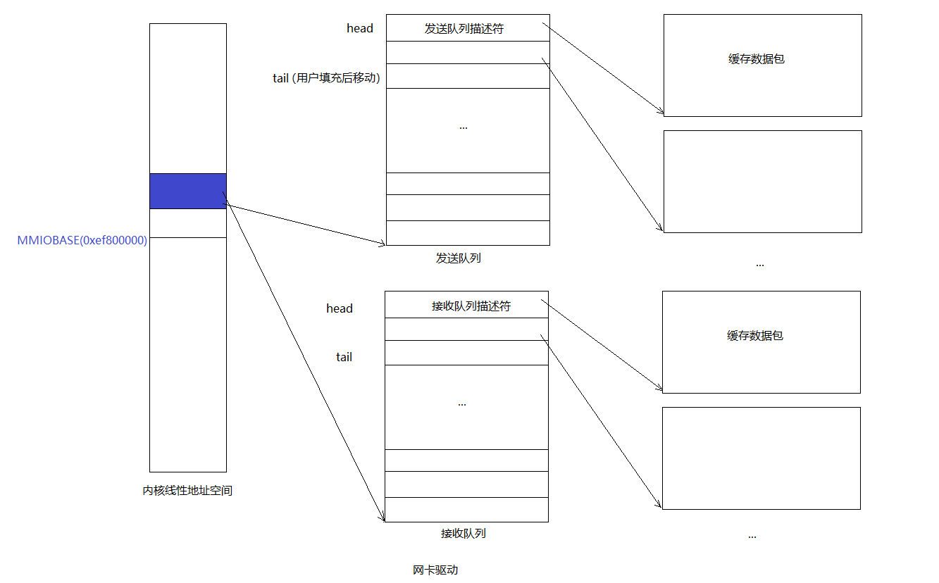 对于传输队列来说是一个典型的生产者-消费者模型:
- 生产者:用户进程。通过系统调用往tail指向的描述符的缓存区添加包数据,并且移动tail。
- 消费者:网卡。通过DMA的方式直接从head指向的描述符对应的缓冲区拿包数据发送出去,并移动head。 接收队列也类似。
Transmitting Packets: Network Server
这是PartA的最后一个部分了。既然你现在有了一个syscall interface作为驱动设备的transmit side,那么我们现在就可以测试数据发送了。
The output helper environment的目标是从核心网络服务接收NSREQ_OUTPUT的IPC信息,然后将packets accompanying these IPC message通过刚刚实现的syscall发送到网络设备驱动。其中NSREQ_OUTPUT的IPC信息会被the low_level_output function in net/lwip/jos/jif/jif.c发送,which glues the lwIP stack to JOS’s network system. Each IPC will include a page consisting of a union Nsipc with the packet in its struct jif_pkt pkt field (see inc/ns.h). struct jif_pkt looks like
struct jif_pkt {
    int jp_len;
    char jp_data[0];
};
jp_len表示了一个packet的长度。在IPC page中所有剩余的bytes都是packet contents。在struct末尾使用size为0的array,即jp_data[0],是一个常见的c技巧,用于表示没有预先确定的长度的缓冲区。由于C不会进行array bounds的checking,只要您确保在struct后有足够的未使用的内存,就可以把jp_data当做任何大小的数组一样使用。
当设备驱动的transmit queue没有空间的时候(full),我们需要注意设备驱动,the output environment和core network server之间的的交互。core network server使用IPC messages发送packets到output environment。如果output environment因为driver没有更多的buffer space来存储新的packets而在一次send packet system call之后suspended了,core network server将会被block,以等待output server来接受这次的IPC call。
Exercise 8. Implement
net/output.c这里注意把之前在e1000_init中的测试发送数据包的代码去掉。
output helper environment的任务是,执行一个无限循环,在该循环中接受核心网络进程的IPC请求,解析该请求,然后使用系统调用发送数据到JOS内核中,之后由内核交由网卡硬件E1000处理。
//net/output.c
//这里就是output helper env的代码
#include "ns.h"
extern union Nsipc nsipcbuf;
void output(envid_t ns_envid){

	binaryname = "ns_output";
	// LAB 6: Your code here:
	// 	- read a packet from the network server
	//	- send the packet to the device driver
	uint32_t whom;
	int perm;
	int32_t req;
	while(1){
		req = ipc_recv((envid_t *)&whom, &nsipcbuf, &perm); 	//accept requests from core network env
		if(req != NSREQ_OUTPUT){
			cprintf("not a type of nsreq output IPC");
			continue;
		}
		struct jif_pkt *pkt = &(nsipcbuf.pkt);
		while (sys_packet_try_send(pkt->jp_data, pkt->jp_len) < 0) // send packet through syscall
		{
			sys_yield();
		}

	}
}
You can use net/testoutput.c to test your output code without involving the whole network server.
#include "ns.h"

#ifndef TESTOUTPUT_COUNT
#define TESTOUTPUT_COUNT 10
#endif

static envid_t output_envid;

static struct jif_pkt *pkt = (struct jif_pkt*)REQVA;

//以下这段代码是内核中的测试代码,和core network server中的low_level_output类似
//主要用于往output helper env发一个IPC消息
void
umain(int argc, char **argv)
{
	envid_t ns_envid = sys_getenvid();
	int i, r;

	binaryname = "testoutput";

	output_envid = fork(); //新建一个 output helper env
	if (output_envid < 0)
		panic("error forking");
	else if (output_envid == 0) {
		output(ns_envid);  //子进程作为output helper env,调用exercise 8中的函数
		return;
	}

	for (i = 0; i < TESTOUTPUT_COUNT; i++) {
		if ((r = sys_page_alloc(0, pkt, PTE_P|PTE_U|PTE_W)) < 0) //分配空间存放pkt
			panic("sys_page_alloc: %e", r);
        //写入"Packet %02d"到pkt的content部分
		pkt->jp_len = snprintf(pkt->jp_data, PGSIZE - sizeof(pkt->jp_len), "Packet %02d", i);
		cprintf("Transmitting packet %d\n", i);
        //发送NSREQ_OUTPUT IPC消息到output_envid中
		ipc_send(output_envid, NSREQ_OUTPUT, pkt, PTE_P|PTE_W|PTE_U);
		sys_page_unmap(0, pkt);
	}

	// Spin for a while, just in case IPC's or packets need to be flushed
	for (i = 0; i < TESTOUTPUT_COUNT*2; i++)
		sys_yield();
}
以上代码和jif/jif.c中的low_level_output函数很相似:
/*
 * low_level_output():
 *
 * Should do the actual transmission of the packet. The packet is
 * contained in the pbuf that is passed to the function. This pbuf
 * might be chained.
 *
 */
static err_t
low_level_output(struct netif *netif, struct pbuf *p)
{
    int r = sys_page_alloc(0, (void *)PKTMAP, PTE_U|PTE_W|PTE_P);
    if (r < 0)
	panic("jif: could not allocate page of memory");
    struct jif_pkt *pkt = (struct jif_pkt *)PKTMAP;

    struct jif *jif;
    jif = netif->state;

    char *txbuf = pkt->jp_data;
    int txsize = 0;
    struct pbuf *q;
    for (q = p; q != NULL; q = q->next) {
	/* Send the data from the pbuf to the interface, one pbuf at a
	   time. The size of the data in each pbuf is kept in the ->len
	   variable. */

	if (txsize + q->len > 2000)
	    panic("oversized packet, fragment %d txsize %d\n", q->len, txsize);
	memcpy(&txbuf[txsize], q->payload, q->len);
	txsize += q->len;
    }

    pkt->jp_len = txsize;

    ipc_send(jif->envid, NSREQ_OUTPUT, (void *)pkt, PTE_P|PTE_W|PTE_U);
    sys_page_unmap(0, (void *)pkt);

    return ERR_OK;
}
Try running make E1000_DEBUG=TXERR,TX run-net_testoutput. You should see something like
Transmitting packet 0
e1000: index 0: 0x271f00 : 9000009 0
Transmitting packet 1
e1000: index 1: 0x2724ee : 9000009 0
...
and tcpdump -XXnr qemu.pcap should output
reading from file qemu.pcap, link-type EN10MB (Ethernet)
-5:00:00.600186 [|ether]
	0x0000:  5061 636b 6574 2030 30                   Packet.00
-5:00:00.610080 [|ether]
	0x0000:  5061 636b 6574 2030 31                   Packet.01
...
To test with a larger packet count, try make E1000_DEBUG=TXERR,TX NET_CFLAGS=-DTESTOUTPUT_COUNT=100 run-net_testoutput. If this overflows your transmit ring, double check that you’re handling the DD status bit correctly and that you’ve told the hardware to set the DD status bit (using the RS command bit).
Your code should pass the testoutput tests of make grade.
